note to begin – I cannot upload video direct from the computer to this page so if you want to see the code in action please put it into a processing sketch.
What do I want to achieve?
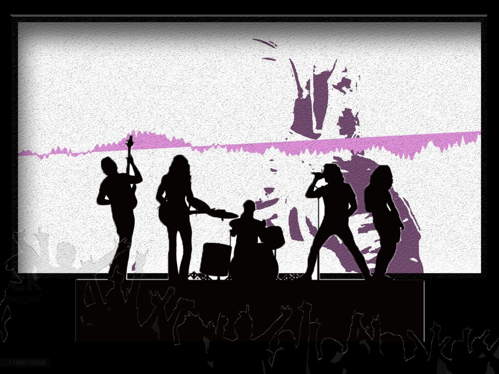
My aim of this project is to create a live projection of a music visualiser that is affected by motion detection in a way to try and create a ‘digital landscape’
a concept like this is from old winAmp visualistations – in particular timestamp 44.36
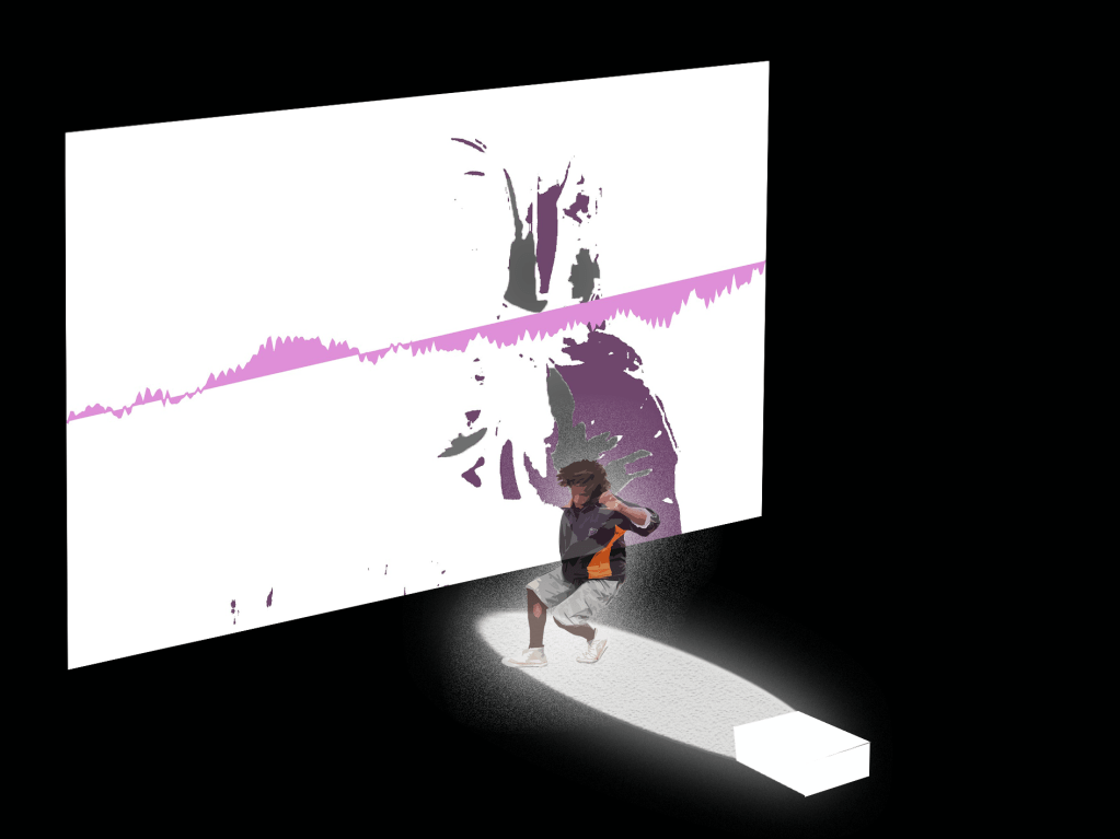
by detecting someone dancing live to the music, I can create ‘snapshots’ of waveforms at the point of the largest movements.
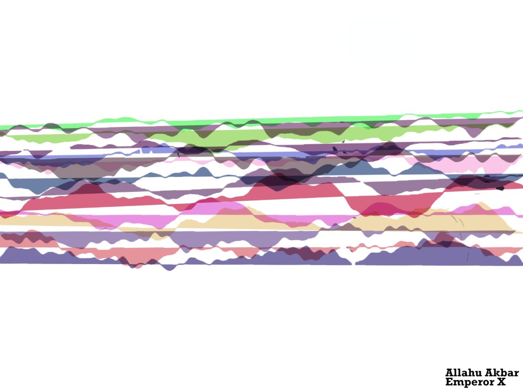
I then want to overlay these ‘snapshots’ and slowly build up an abstract landscape with peaks and valleys and everything in between. Each song should have its own unique digital landscape.
in this way my code should flow from a digital to physical and then back to digital .
immediate thoughts about how this would be used is in a live music environment, most visualisation projections I see are pre built/rendered – i want to see something that reacts in real time to the music and room.
Another potential is using the digital landscapes to re-output into a print, so someone can have a manifestation of their reaction to their favourite songs. This link was a quick find on music visualisation posters
https://fineartamerica.com/shop/posters/music+visualization
My Coding Adventure
I decided I am going to work in processing
first of all, it is the language/application I am most comfortable creating in.
Second, I want to initially try this concept as a 2D plane, where the sense of depth in the landscape will come from the way the waveforms are overlayed.
A breakdown of my approach to this project
- Work out video capture and motion detection
- Create a visualiser I think will generate interesting landscape forms
- put the two together into one sketch
- Turn the frames of the visualiser into a manipulatable object
- place that new object onto the sketch
Video capture and Motion Detection
My first task was to capture video
for this I found a useful video by coding train, which summarised the theory and put into practice
11.1: Capture and Live Video – Processing Tutorial
Through this I wrote this code
import processing.video.*;
Capture video;
void setup() {
fullScreen();
video = new Capture(this,width,height,30);
video.start();
}
void captureEvent(Capture video) {
video.read();
}
void draw() {
//if (video.available()) {
//video.read(); – used to read video before setting up another void
image(video,0,0);
}
This is done using the video library built into processing. My main deviations from the code I worked off of was using fullScreen() because I wanted to try and move away from hardcoding my work (and I would like the project as a full screen).
An interesting bit I learned was that by creating a new void captureEvent I could avoid the code having to continually repeat the if video available statement each loop in draw, simplifying the code.
Motion detection
This was the part of the project that I thought would be the hardest and I was most apprehensive about, with my limited skillset.
luckily coding train once again came to the rescue after looking up multiple resources. In my search I came across this article, which was a really cool read about the ways in which others have used different toolkits to create an array of fun modifications of their video feeds, or sensing people in environments.
https://openframeworks.cc/ofBook/chapters/image_processing_computer_vision.html
11.6: Computer Vision: Motion Detection – Processing Tutorial
From this tutorial I was able to get two pieces of information crucial to the motion detection. A way to read all the pixels on screen and an algorithm that looked at this distribution – which then was compared to a frame of the previous pixel array.
import processing.video.*;
Capture video;
PImage prev;
float threshold = 25;
float motionX = 0;
float motionY = 0;
float lerpX = 0;
float lerpY = 0;
void setup() {
fullScreen();
video = new Capture(this,width,height,30);
video.start();
prev = createImage(width,height,RGB);
}
void captureEvent(Capture video) {
//allows the previous image to be overlayed/copied with the capture
prev.copy(video,0,0,video.width,video.height,0,0,prev.width,prev.height);
prev.updatePixels();
video.read();
}
void draw() {
//if (video.available()) {
//video.read(); – used to read video before setting up another void
video.loadPixels();
prev.loadPixels();
image(video,0,0);
threshold = 50;
int count = 0;
float avgX = 0;
float avgY = 0;
loadPixels();
//loops through pixels
for (int x = 0; x < video.width; x++) {
for (int y = 0; y < video.height; y++) {
int loc = x + y * video.width;
//current colour check for both previous and new image – allows use on any background with any clothing (as long as different)
color currentColor = video.pixels[loc];
float r1 = red(currentColor);
float g1 = green(currentColor);
float b1 = blue(currentColor);
color prevColor = prev.pixels[loc];
float r2 = red(prevColor);
float g2 = green(prevColor);
float b2 = blue(prevColor);
float d = distSq(r1,g1,b1,r2,g2,b2);
if (d > threshold*threshold) {
//if variable for if threshold average is greater or equal turns pixel black or white
avgX += x;
avgY += y;
count++;
pixels[loc] = color(255);
} else {
pixels[loc] = color(0);
}
}
}
//very important to update pixels
updatePixels();
//tracking of average pixel movement
if (count > 200) {
motionX = avgX / count;
motionY = avgY / count;
}
//shows the pixel being tracked – do not want in final product
lerpX = lerp(lerpX, motionX, 0.1);
lerpY = lerp(lerpY, motionY, 0.1);
fill(255, 0, 255);
strokeWeight(2.0);
stroke(0);
ellipse(lerpX, lerpY, 36, 36);
}
float distSq(float x1, float y1, float z1, float x2, float y2, float z2) {
float d = (x2-x1)(x2-x1) + (y2-y1)(y2-y1) +(z2-z1)*(z2-z1);
return d;
}
this code uses a lot of float variables – which would normally sit outside the setup function – though here it was important to include in the draw as the variable is constantly being reassessed. The other thing I learnt about was arrays and int functions. In this case An array is used to check all the pixels along the width and height of the screen.
these values are then run through to check their RGB values – and against the threshold^2 of movement. If the threshold is reached then all those pixels become black.
The other little bit is using CodingTrains video I added in a little ellipse that could show me in real time that the tracking was working – though i would not have this in the final product, it is usual for testing. This looks a the average movement of the pixels to create a point considered the locus of the movement. While the ellipse wont be in the final product, I could use this to be the arbitrary factor which decides when the visualiser is captured.
If I was to continue further with this sketch, I would love to fill in the space between the edges of the movement to have a full shape of the human/object moving. I think this could be achieved using blob detection but haven’t looked into it as I quite like the current effect. I don’t want the motion detection imagery to impact on the main visualiser being the focus
Visualiser
attempt 1
I was intially thinking about creating a visualisation much like an old itunes style using bars that rose based on the amount of noise from a particular sample size. I know that I didnt want to have the landscape generation be left heavy (which is where the visualisation of the bass goes normally – but i could put that into the centre and get it to spread out that way.
this video was interesting in using a midi setup to influence the visualisation of sound, but it wasn’t quite what I was looking for – but a future avenue of interest. especially in a live music setting.
Instead I found this video Audio Visualizer Using Processing
It created
import ddf.minim.analysis.; import ddf.minim.;
Minim minim;
AudioPlayer jingle;
AudioOutput output;
FFT fft;
int[][] colo=new int[300][3];
//AudioIn in;
void setup() {
size(480, 320);
//fullScreen();
noCursor();
minim = new Minim(this);
output = minim.getLineOut();
fft = new FFT(output.bufferSize(), output.sampleRate());
// textFont(createFont(“Arial”, 16));
// windowName = “None”;
}
void draw()
{
background(0);
stroke(255);
fft.forward(output.mix);
for(int i = 0; i < fft.specSize(); i++) {
ellipse(i,200,7,fft.getBand(i)*10);
}
}
I wasnt sold on the output of this approach. And I felt the reference I was using was more complicated than it needed to be. This is also where I first ran into the problem of processing not registering computer audio as its own input, it only wanted to take sound from inputs such as microphone. Through a bit of looking it seemed I needed to somehow turn the comp output of the music into an input. I wanted the direct output so the music visual wouldn’t be impacted by external sources – important in a live setting which is loud and has a lot of other noise sources.
https://forum.processing.org/one/topic/how-to-get-sound-from-computer-output.html
seemed to be two options
use a virtual audio interface like soundflower(MacOs) to mimic the output as input to be picked up by the program in the fft.
find an actual way within the minim/sound library.
I didnt want to complicate the process of making my sketch work with external apps, and there seems no way within the processing libraries to do as I want. luckily a third option appeared – by enabling stereo mix in my sound settings (windows) I could set the speakers of the system as an udio input for processing to read 🙂
Attempt 2
because I wasn’t happy with the first attempt, I decided to just look through the processing reference library – and learnt to operate within the stock sound library to analyse sound
https://processing.org/reference/libraries/sound/FFT_analyze_.html
https://processing.org/reference/libraries/sound/Waveform.html
I ended up with this code
import processing.sound.*;
FFT fft;
AudioIn in;
Waveform waveform;
int samples = 600;
public void setup()
{
size(640, 360);
background(255);
fft = new FFT(this);
in = new AudioIn(this, 0);
waveform = new Waveform(this, samples);
waveform.input(in);
}
public void draw()
{
background(50);
stroke(255);
strokeWeight(2);
noFill();
waveform.analyze();
beginShape();
for(int i = 0; i < samples; i++)
{
vertex(
map(i, 0, samples, 0, width),
map(waveform.data[i], -1, 1, 0, height)
);
}
endShape();
}
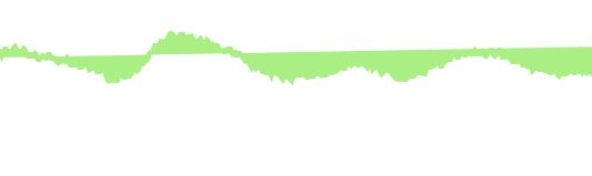
This felt much simpler and i really liked the effect of the stock shape created by the reference. This not only has to do with the shape by the fact that I am now analysing the waveform of the sound whereas before i was looking at bands.
the new info I learnt from this was about map and the shape function. By using begin and close shape you can map any number of vertices you like to create your own shape. here a map is used – which remaps a number from one range to another (in this case vertices) which allows for the variation based on data across a shape.
to continue to make it visually appealing I further modified the code – changing it to full screen and adding a random RGB generator which i used as variables to influence all levels of the shape colour and size. as a result was this.
import processing.sound.*;
FFT fft;
AudioIn in;
Waveform waveform;
int samples = 512;
public void setup()
{
fullScreen();
colorMode(RGB);
fft = new FFT(this);
in = new AudioIn(this, 0);
waveform = new Waveform(this, samples);
waveform.input(in);
}
public void draw()
{
float R = random(0,255);
float G = random(0,255);
float B = random(0,255);
background(50);
stroke(R,G,B);
strokeWeight(R);
noFill();
waveform.analyze();
beginShape();
for(int i = 0; i < samples; i++)
{
vertex(
//width of the ‘line’
map(i, 0, samples, 0, width),
//starting position of ‘line’ with height
map(waveform.data[i], -1, 1, 0, height)
);
}
endShape();
}
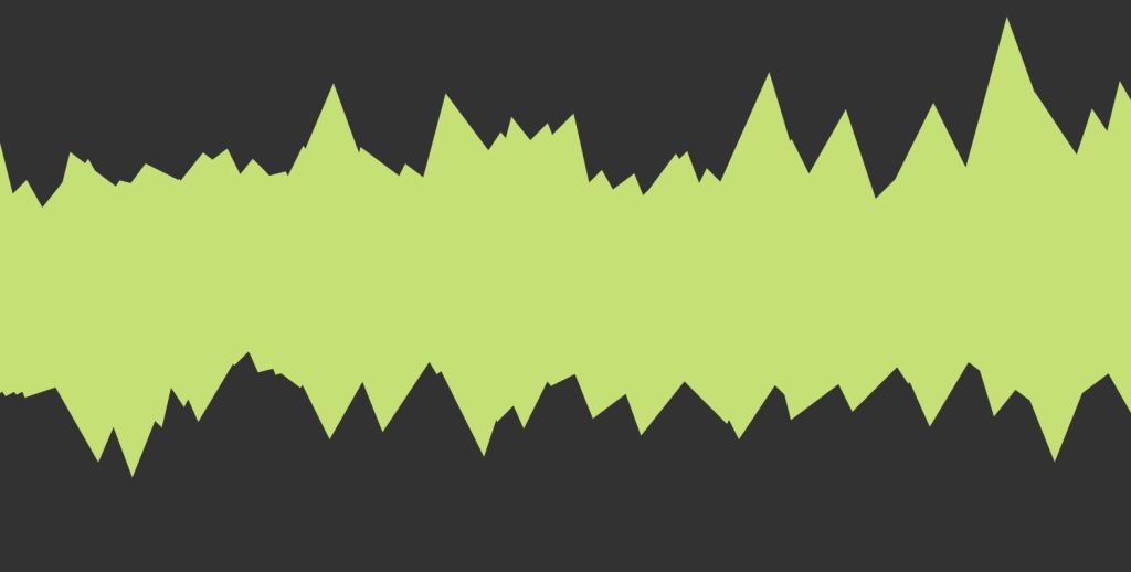
While fun was a bit extreme so decided to pull back from the amount of aspects impacted by the generators. Instead making strokeWeight(5) and making stroke affected by RGB. I also added a fill affected by RGB because I liked the shape as one mass, which I thought made it look more like a landscape.
Putting the two together
I thought this step would be very simple, but it still had its challenges.
Initially had a lot of trouble getting the code to work
The main problem ended up being the placement of the float algorithm in the draw function
float distSq(float x1, float y1, float z1, float x2, float y2, float z2) {
float d = (x2-x1)(x2-x1) + (y2-y1)(y2-y1) +(z2-z1)*(z2-z1);
return d;
}
Once I placed the float variable at the top with the other floats both worked together without interference
- at first I thought it was an overlay problem so I tried to work in P3D which was disastrous as none of the code was set up to operate in a 3d environment
I was worried about one image overlaying the other
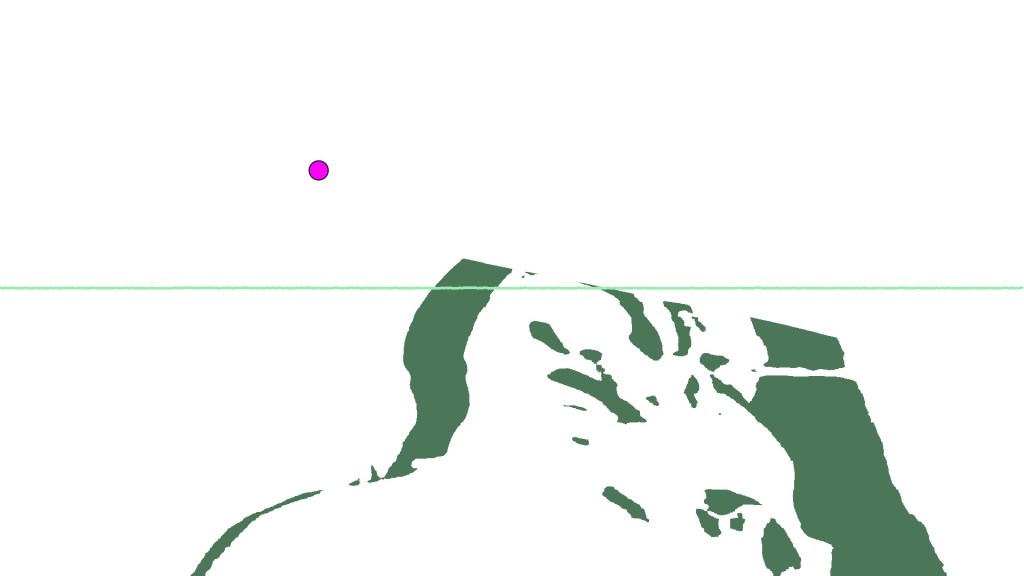
But once I removed the background from the visualizer code the video image became the background which acted to clear the visualiser 🙂
Made some tweaks to the coloration of the pixel locators to match more with the RGB movement of the visualiser
the code ended up looking like this
import processing.video.; import processing.sound.;
FFT fft;
AudioIn in;
Waveform waveform;
int samples = 512;
Capture video;
PImage prev;
float threshold = 100;
float motionX = 0;
float motionY = 0;
float lerpX = 0;
float lerpY = 0;
float distSq(float x1, float y1, float z1, float x2, float y2, float z2) {
float d = (x2-x1)(x2-x1) + (y2-y1)(y2-y1) +(z2-z1)*(z2-z1);
return d;
}
void setup() {
fullScreen();
video = new Capture(this,width,height,0);
video.start();
prev = createImage(width,height,RGB);
fft = new FFT(this);
in = new AudioIn(this, 0);
waveform = new Waveform(this, samples);
waveform.input(in);
}
void captureEvent(Capture video) {
prev.copy(video,0,0,video.width,video.height,0,0,prev.width,prev.height);
prev.updatePixels();
video.read();
}
void draw() {
float R = random(100,255);
float G = random(100,255);
float B = random(100,255);
video.loadPixels();
prev.loadPixels();
image(video,0,0);
int count = 0;
float avgX = 0;
float avgY = 0;
loadPixels();
for (int x = 0; x < video.width; x++) {
for (int y = 0; y < video.height; y++) {
int loc = x + y * video.width;
color currentColor = video.pixels[loc];
float r1 = red(currentColor);
float g1 = green(currentColor);
float b1 = blue(currentColor);
color prevColor = prev.pixels[loc];
float r2 = red(prevColor);
float g2 = green(prevColor);
float b2 = blue(prevColor);
float d = distSq(r1,g1,b1,r2,g2,b2);
if (d > threshold*threshold) {
avgX += x;
avgY += y;
count++;
pixels[loc] = color(R/2,G/2,B/2);
} else {
pixels[loc] = color(255);
}
}
}
//very important to update pixels
updatePixels();
if (count > threshold*threshold) {
motionX = avgX / count;
motionY = avgY / count;
}
lerpX = lerp(lerpX, motionX, 0.1);
lerpY = lerp(lerpY, motionY, 0.1);
fill(255, 0, 255);
strokeWeight(2.0);
stroke(0);
ellipse(lerpX, lerpY, 36, 36);
stroke(R,G,B);
strokeWeight(5);
fill(R,G,B);
waveform.analyze();
beginShape();
for(int i = 0; i < samples; i++)
{
vertex(
map(i, 0, samples, 0, width),
map(waveform.data[i], -1, 1, 0, height)
);
}
endShape();
}
Making the visualiser into a manipulable image
My aim here was to capture a frame of the visualiser at point of movement detection threshold and translate it to the top of the screen
Something along the lines of in non code language
If statement in motion detection
if Avg movement > X {
Capture frame of shape}
Then overlay that shape onto the processing sketch
Translate to the top of screen
For each subsequent image Y++ to move the images down the screen in increments
To do this I was thinking about creating a lot more void events to allow easier callbacks in the draw function
Such as placing shape creation in a void display()
I tabbed out all the different processes and it made the page feel clean 🙂
I learnt about Pshapes and PImage to manipulate imagery loaded in through the data folder. the dream was being able to turn just the shape display into an image without having to go through a loading process outside of the sketch such as saving an image then reloading it.
An idea was to use classes to create a p shape from the draw function ? Which i quickly found didnt really change the base level that processing wasnt really built to deal with created shapes within a sketch in this way. I wanted a separate shape generated based on the visualiser to manipulate.
I was confusing myself or making it more difficult than needed
So I went back to just thinking about voids
I created a captureEvent
This contained the saveFrame function that made an image in the folder
Could rename file series for easier use later
in the draw function i added this
if(mousePressed) {
captureEvent();
}
which corresponded to
saveFrame(dataPath(“frame###.jpg” ));
I also wanted to load the image there in that void event (which is why I made it a separate call from draw) which I very quickly found processing doesn’t like 😦
this threw my entire life for a loop. Processing only considers images in a sketches data folder after it refreshes the sketch – which is not what I wanted to do. I was running out of time at this point, an unfortunate coincidence that the rest of the project took so long for me to figure out it had never considered to me that this would be the bit that broke the dream.
I tried a new approach with just saveImage()
Save image – worried that overlaying the image it will cover everything else happening on screen
Found a nice reference to mask the image – can just modify it to fit the current random values of my draw
The next problem I ran into was a build up of files in the data folder – which ideally i would want the sketch to delete before it closed. I found reference to remove files using java.io
import java.io.File;
String fileName;
void setup() {
size(480, 360);
background(0);
ellipse(width/2, height/2, width/2, height/2);
fill(255);
save(dataPath(“image1.jpg”)); // save in datapath
}
void draw() {
}
void mousePressed() {
fileName = dataPath(“image1.jpg”);
File f = new File(fileName);
if (f.exists()) {
println(“deleting”);
f.delete();
}
}
but when I implemented this into my own code it didn’t work – after spending hours on this I gave up in frustration
I GIVE UP MOVEMENT (from my notes) – idea of last approach to the idea before stuck
-Images do not want to load within the draw function as I need so I will have to create another processing sketch to run after the other to place the shapes in position
-I am now determining the right numbers for the saveFrame for a camera about 2 meters away so the whole body is in shot
-When using an if statement that looks at the avg movement of y and x vs. their height and width/1.5 generates about the right number of images 100 to 500 range
CREATE A NEW SKETCH TO MAKE LANDSCAPE.
this theoretically should have worked just fine?
I made this code up based on my understanding of array’s and Pimages. this should theoretically have made processing happy but there were two fatal parts to this. One was that I could not figure out how to get this sketch to read from my other sketches data folder without creating an absolute path which is hardcoding this sketch to my computer. and Second, was that the images would not load anyway even when in the correct data folder for this sketch! I got an image to load if i put in its exact frame number – but as soon as I put it into an array it broke. Here is the sketch of my last ditch attempt to make this project work in the way I had hoped.
PImage frame;
PImage [] frames = new PImage[1000];
boolean a = true;
void setup() {
fullScreen();
for (int i=0; i < frames.length; i ++) {
if(!a){
loadImage(dataPath(“frame”+i+”.jpg”));
loop();
}else{
frames[i] = loadImage(dataPath(“frame”+i+”.jpg”));
}
}
}
void draw () {
for (int i=0; i < frames.length; i ++) {
int index = int(random(0,frames.length));
;
}
}
Thoughts and Reflections
I feel like this project is still possible with tinkering or someone more knowledgeable of code. I would have liked to have more interaction with my lecturers surrounding this but my situation just did not allow me the time this half of the semester to engage in the classes as I would have wished. Unluckily by the time I had reached the point I realised this wouldn’t work as I wanted I was less than a day away from hand in. Google did not come to aid me.
Other approaches I have thought about since then is to input into photoshop and manually generate a poster with images from the visualiser. I might create a mock up of this process. The other thing was I could not find a perfect way to save just a frame at the maximum point of movement of the motion detector, again I am sure there is a way but my maths and code knowledge has not currently thought of it. This means there is a bit of slowdown in the sketch when multiple frames are being saved, I don’t mind it, but I would prefer it not to happen.
All in all, I was really excited for this project – I really like interactive media/art, I find it gets people more immediately engaged with a space in a way other mediums don’t not to mention making ideas more accessible and playful. I am disappointed I could not realise it in the timeframe but I think it represents a basis for future exploration and work, despite it being maybe to ambitious for me currently.
My final code – I encourage you to input into processing to see the full effect.
import processing.video.;
import processing.sound.;
FFT fft;
AudioIn in;
Waveform waveform;
int samples = 512;
int i=0;
Capture video;
PImage prev;
float threshold = 100;
float motionX = 0;
float motionY = 0;
float distSq(float x1, float y1, float z1, float x2, float y2, float z2) {
float d = (x2-x1)(x2-x1) + (y2-y1)(y2-y1) +(z2-z1)*(z2-z1);
return d;
}
void setup() {
fullScreen();
video = new Capture(this,width,height,0);
video.start();
prev = createImage(width,height,RGB);
fft = new FFT(this);
in = new AudioIn(this, 0);
waveform = new Waveform(this, samples);
waveform.input(in);
}
void captureEvent(Capture video) {
prev.copy(video,0,0,video.width,video.height,0,0,prev.width,prev.height);
prev.updatePixels();
video.read();
}
void draw() {
float R = random(100,255);
float G = random(100,255);
float B = random(100,255);
video.loadPixels();
prev.loadPixels();
image(video,0,0);
int count = 0;
float avgX = 0;
float avgY = 0;
loadPixels();
for (int x = 0; x < video.width; x++) {
for (int y = 0; y < video.height; y++) {
int loc = x + y * video.width;
color currentColor = video.pixels[loc];
float r1 = red(currentColor);
float g1 = green(currentColor);
float b1 = blue(currentColor);
color prevColor = prev.pixels[loc];
float r2 = red(prevColor);
float g2 = green(prevColor);
float b2 = blue(prevColor);
float d = distSq(r1,g1,b1,r2,g2,b2);
if (d > threshold*threshold) {
avgX += x;
avgY += y;
count++;
pixels[loc] = color(R/2,G/2,B/2);
} else {
pixels[loc] = color(255);
}
}
}
//very important to update pixels
updatePixels();
if (count > threshold*threshold) {
motionX = avgX / count;
motionY = avgY / count;
}
stroke(R,G,B);
strokeWeight(5);
fill(R,G,B);
waveform.analyze();
beginShape();
for(int i = 0; i < samples; i++)
{
vertex(
map(i, 0, samples, 0, width),
map(waveform.data[i], -1, 1, 0, height)
);
}
endShape();
if((motionX >= width/1.5) && (motionY >= height/1.5)){
saveFrame(dataPath(“frame###.jpg” ));
}
}
the main distinctions from previous sketches code is the if statement at the bottom to create a save frame based on a threshold of motion Y and motion X
the ellipse has been deleted to make it more visually appealing – so the lerp functions were no longer needed.
The R G and B values were slightly modified for the motion detection to differentiate it/sit back from the visualiser.